In this blog, I would like to introduce to you one of my latest hobbies – Internet of Things (IoT). We will go through a short intro and then jump directly into creating some cool “things” connected to the internet. This tutorial will help you create two simple (yet very useful) creations that could make your life easier. And of course, as I’m a Cloud Specialist, we will try to “touch” the Cloud in the second guide :). Dig in.
So, what does the “Internet of Things” buzzword mean? It’s just a connection of various physical devices that exchange data. It’s as simple as that. Nowadays, almost everything is connected to the internet and is able to communicate. Multiple devices have different sensors or capabilities that may be connected and benefit from that. That means that your smart fridge, smart vacuum cleaner, smart living room gadgets can be a part of internet of things.
If you wish, you can skip the theory below and jump right to the Creative part below.
Have you ever heard about this term? If not, then I’m pretty sure that you know what Raspberry Pi is. But let’s go back to the term… Embedded system is a combination of hardware and software designed to perform some dedicated function (source: https://barrgroup.com/Embedded-Systems/Glossary-E). We could say that they are just small computers (with CPU, memory, peripherals and so on). So, you don’t have to be afraid that we are going to create printed circuit boards in this article. We are just hobbyists who expect a ready to use system. Exactly for this purpose there are many embedded devices with different configurations and sizes for experimenting, learning, creating prototypes or used as personal computers with installed desktop operating systems. For example, it is Raspberry Pi which is very popular for small home media centers, Beaglebone which I’m using in this blog, Arduino, Banana Pi and many more. You can choose from a broad selection and your choice only depends on your expectations for their functionality.
When we want to work with embedded system and connect hardware to it, we are interested in pins. Pins are those little holes where you’re putting jumper cables. That way you can communicate with the processor. This is what is really great about these little embedded devices. You don’t have to solder anything only connect pieces together. It’s like Lego.
What is important to mention is that two pins don’t have to be exactly the same. Processor provides different types of pins for different purposes. You can find pins for voltage supply, ground, reset, power input/output (I/O), analog, different busses (I2C, SPI …) and so on. You can check pinouts of every board on their homepage. As I already mentioned, check what functionality and features your device has when choosing one.
Basic difference between these two terms are that analog signal is defined as a continuous signal and digital is a discrete time signal. Have you never heard that word before? It means that analog value represents physical measurement so value uses continuous range (for example: 0.5, 0.489, 0.123, etc.). On the other hand, digital value is generated by digital modulation – it’s represented by just two values – one or zero (high and low).
In our creative part we will be using general purpose input/output (GPIO) and analog pins. And of course, we will need power supply and ground. GPIOs, as the name tells, are generic pins where user can choose if they are going to be used as input or output during the runtime. So, the processor is either “listening” what information is coming from the selected pin (1 or 0) or you can specify if the level on the desired pin will be 1 or 0. Analog pins will just receive voltage level on pin as value.
Ok, I understand that few of you skipped right to this part and did not read the boring stuff above. You are right, enough was said, let’s be creative! As you know, every programming guide starts with the Hello world application. Don’t worry, we will skip that too. We are way more awesome and we will begin with something that you can actually use.
Note: both guides are designed for Beablebone Black, but that doesn’t mean that it won’t work for example on Raspberry Pi. I’m pretty sure that it works very similar.
Because internet of things is a connection of physical device and software, we will need some devices. Most of the sensors and cables are really easy to get and they are super cheap (for example motion sensor costs around 1€, raindrop detection sensor is 0.50€, etc.). Embedded devices will cost you more, but remember that you are buying a fully functional computer, not just some unfinished circuit board.
I’ve chosen Beaglebone Black because I need more analog pins for my home project then for example Raspberry provides. But you can choose anything that you want or have, the principle is the same.
In the first guide, we will create a simple notification application that will monitor movement in your room. We will code a simple webservice that will enable you to check the movement status through a HTML webpage. That means that you will be able to see status of your gadget from any device that is able to browse HTML webpages (which is almost anything).
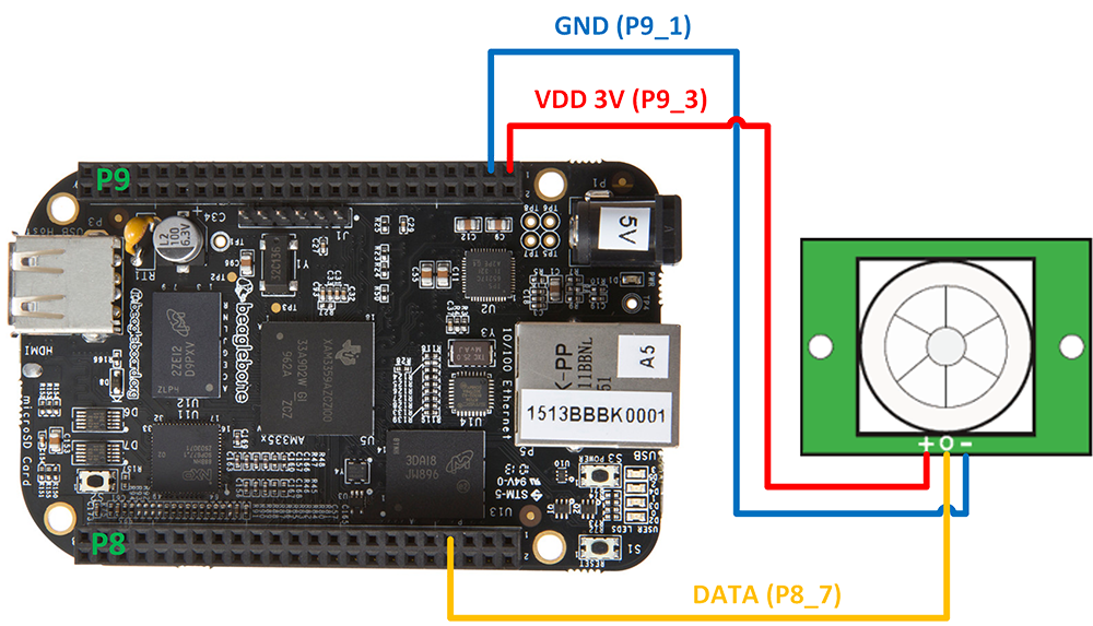
For creating this sample, we won’t need to use the breadboard, although you can if you want. Motion sensor is easy to connect with male-female jumper cables directly to your embedded device. We need to connect our sensor to 3.3V voltage (red) and ground (blue) dedicated to digital pins. Data cable (yellow) will be connected to GPIO pin P8_7 where we’ll be reading digital values. Be careful when connecting sensors. You must not mix the cables! It can destroy your device. Wiring is shown below. At the end, it could look like this.
Note: be careful when connecting analog and digital sensors, each component needs different voltage, ground and data input pins. You can find them on pinout.
When we’re talking about coding our device for digital wiring, we can use a few different methods to tell our device what to do. Either we use the Adafruit library or Bash. Adafruit library is more complex but for testing purposes you can use simple Linux commands as you are used to. I will shortly show you how to use Bash.
cd /sys/class/gpio/
echo 66 > export
echo in > ./gpio66/direction or echo out > ./gpio66/direction
echo 0 > ./gpio66/value or echo 1 > ./gpio66/value
cat ./gpio66/value or cat ./gpio66/value
As you can see it’s very simple. With this you can do bash script and control your OS with hardware devices or sensors. For example. you can turn off your computer by moving your hand across the room.
Note: here is small example of bash commands.
In the following part of the blog, we will be using Adafruit and Python. Now, the wiring is done, so let’s do some really simple coding! Our program should read value of the desired GPIO pin and then decide from the output if there was a movement or not. This result will render different webpage based on the output.
First, we will need to setup our work directory. We’re going to create a movement status webpage so we need two simple HTML pages (movement / no movement). Your directory should look like this:
.
|-- digital.py
`-- templates
    |-- intruder.html
    `-- ok.html
If you’re not familiar with HTML, don’t worry. They are super-simple webpages. They just write “Everything ok” in green font or “Intruder” in red font. You can find them here. And finally, our awesome Python script.
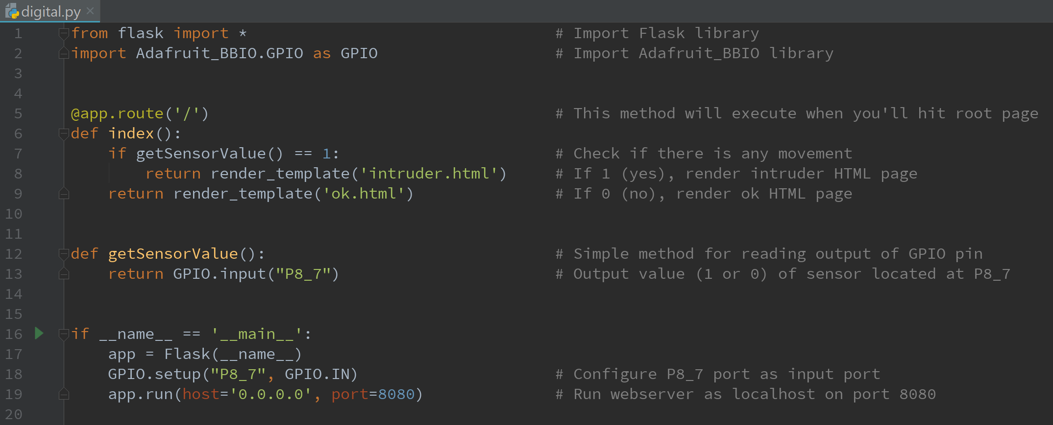
Now it’s time to bring it alive! Your webservice should start and when you open the browser on Beaglebone’s IP and port 8080, you should see that everything is ok. Now try to move your hand in front of the sensor and refresh the page. You should see that some bad intruder has moved into your room.

As you can see working with GPIO pins is just about reading/writing values and react upon the output which will be always either 1 or 0. On trigger, you can run OS command, enable another sensor, send e-mail, SMS, start alert, etc. It’s up to your imagination. All the source codes are downloadable at the end of this blog.
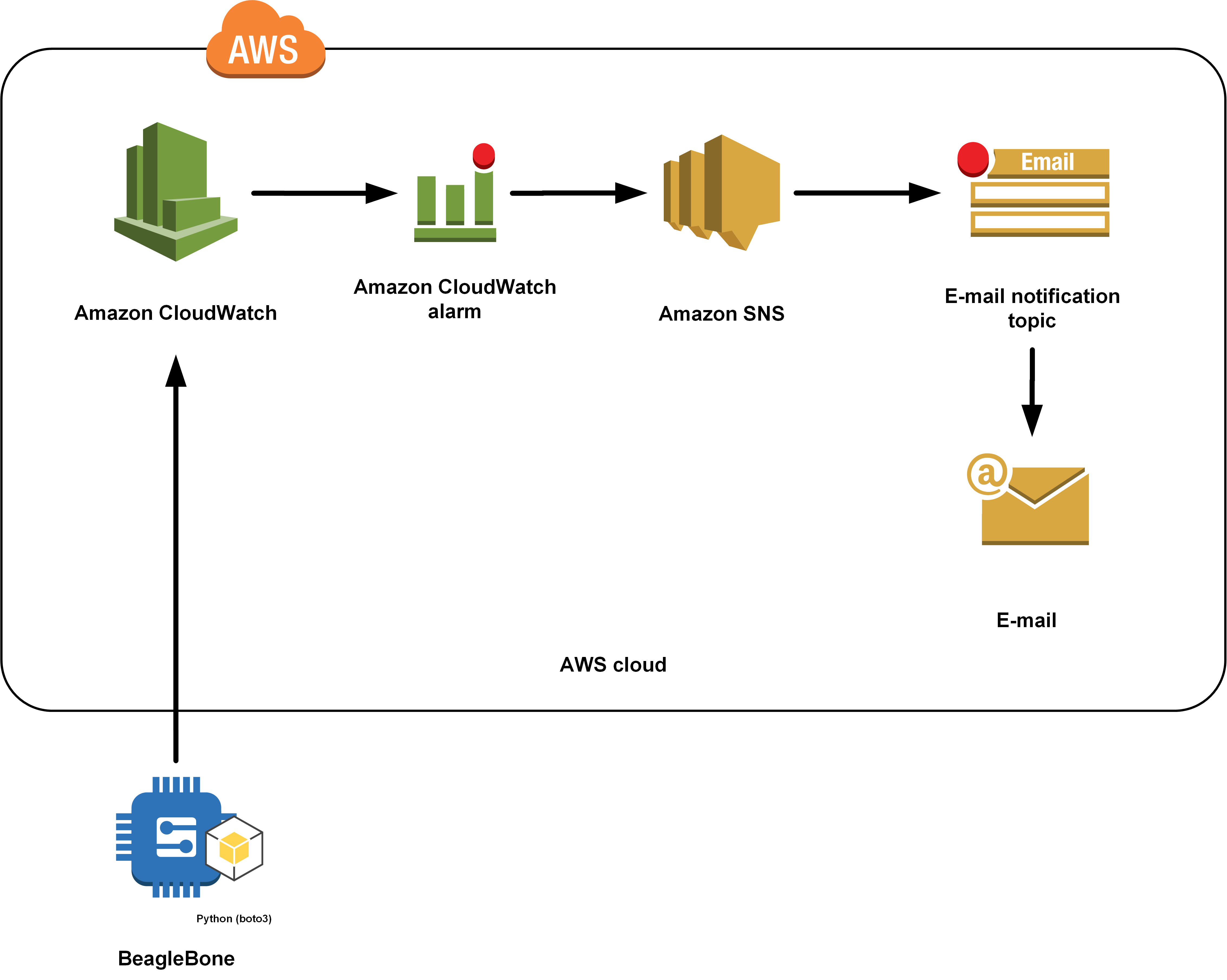
In the second guide, we will create a simple notification application that will monitor temperature of your room and will send e-mail/SMS notification via Amazon AWS Services (AWS CloudWatch and SNS) when the threshold is reached. Of course, you can change usage of Amazon AWS e-mail notification service for the local mail server.
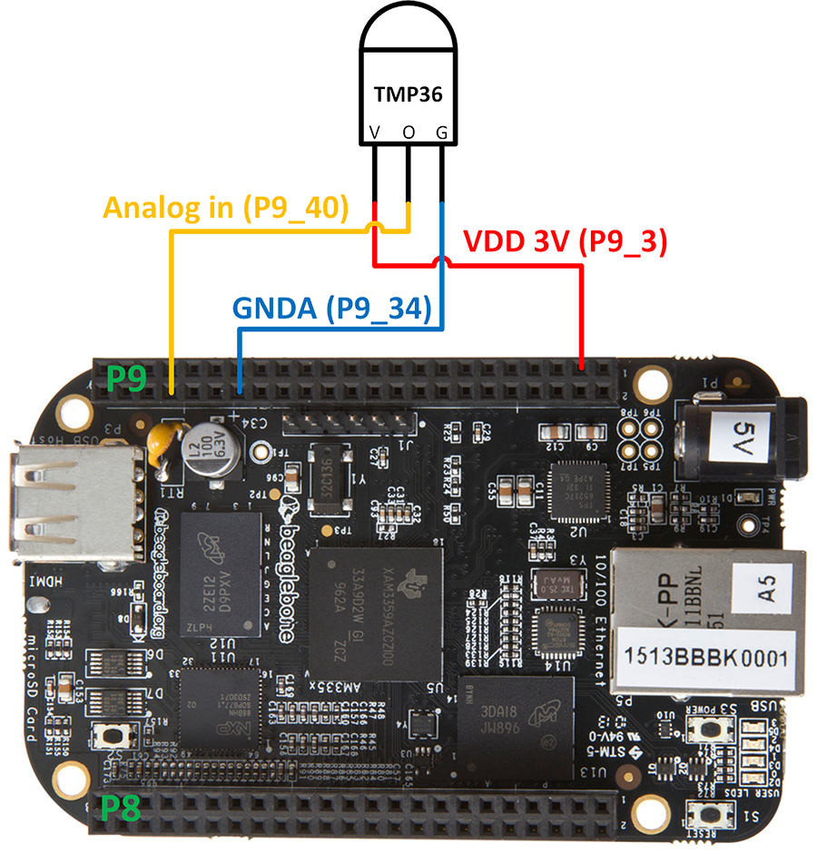
For this sample, we will need a breadboard. You will also need three male-male jumper cables and a temperature sensor. We need to connect our sensor to 3.3V voltage (red) and ground (blue) dedicated to analog pins. Data cable (yellow) will be connected to Analog pin P9_40 where we’ll be reading analog values. Be careful when connecting sensors! You must not mix the cables. It can destroy your device. Wiring is shown below. At the end, it could look like this.
Note: be careful when connecting analog and digital sensors, each component needs different voltage, ground and data input pins. You can find them on pinout.
In this example, we will stick with Adafruit and Python. I believe that you’ve successfully wired your devices and now let’s look what we need to code. We will need a method for reading analog value of the analog pin, do calculations to calculate centigrade degrees, send these values to AWS CloudWatch as custom metric and configure AWS CloudWatch alarm notification for temperature. You will need your AWS credentials (secret and secret access key) to use Python SDK. Here is the code.
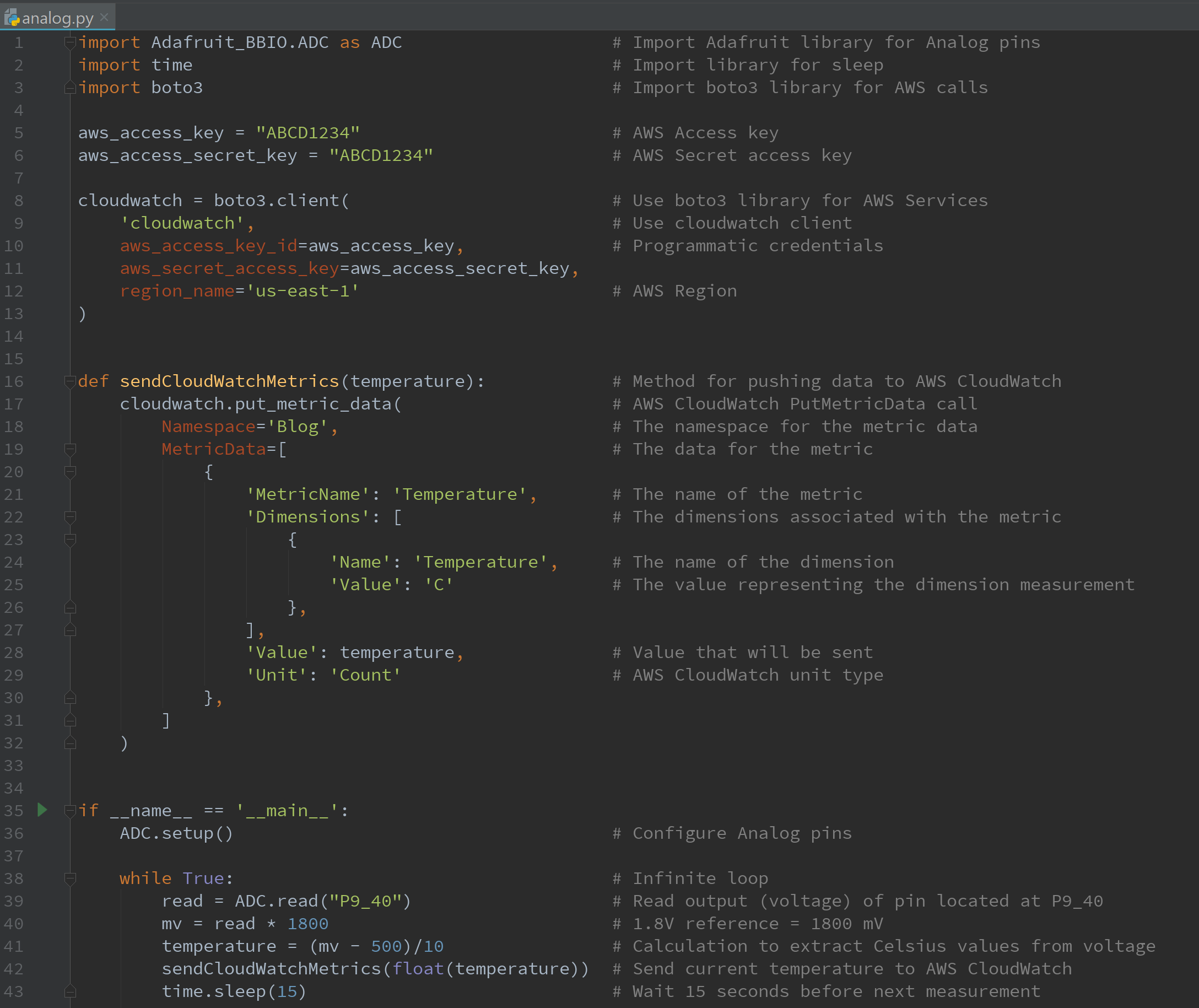
When you’ll run your code, you should start pushing measured metrics to your AWS account every 15 seconds. Then you will see the values as custom metrics in AWS CloudWatch. This is how it should look like:
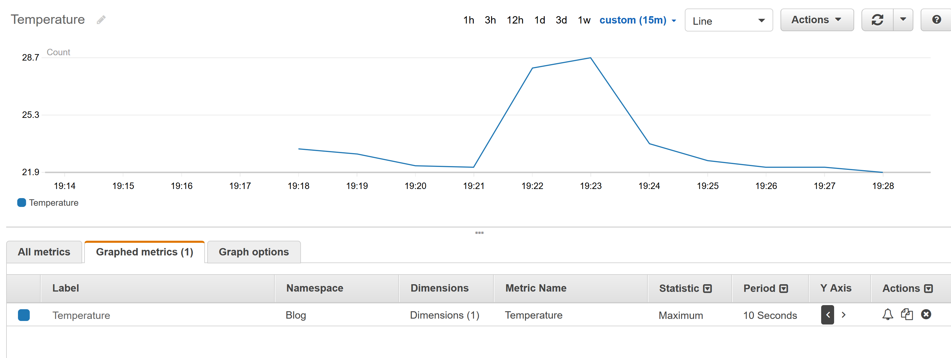
Now we are collecting data from our device which is cool, but let’s make it even cooler. We want to be notified when the temperature in our room reaches a specific threshold. We will need two AWS Services for that. AWS CloudWatch for configuring threshold and triggering alarm, and AWS SNS for sending notifications. In AWS SNS you can choose from multiple ways of delivering notifications – SMS, e-mail or mobile push notifications. The diagram bellow shows these connections.
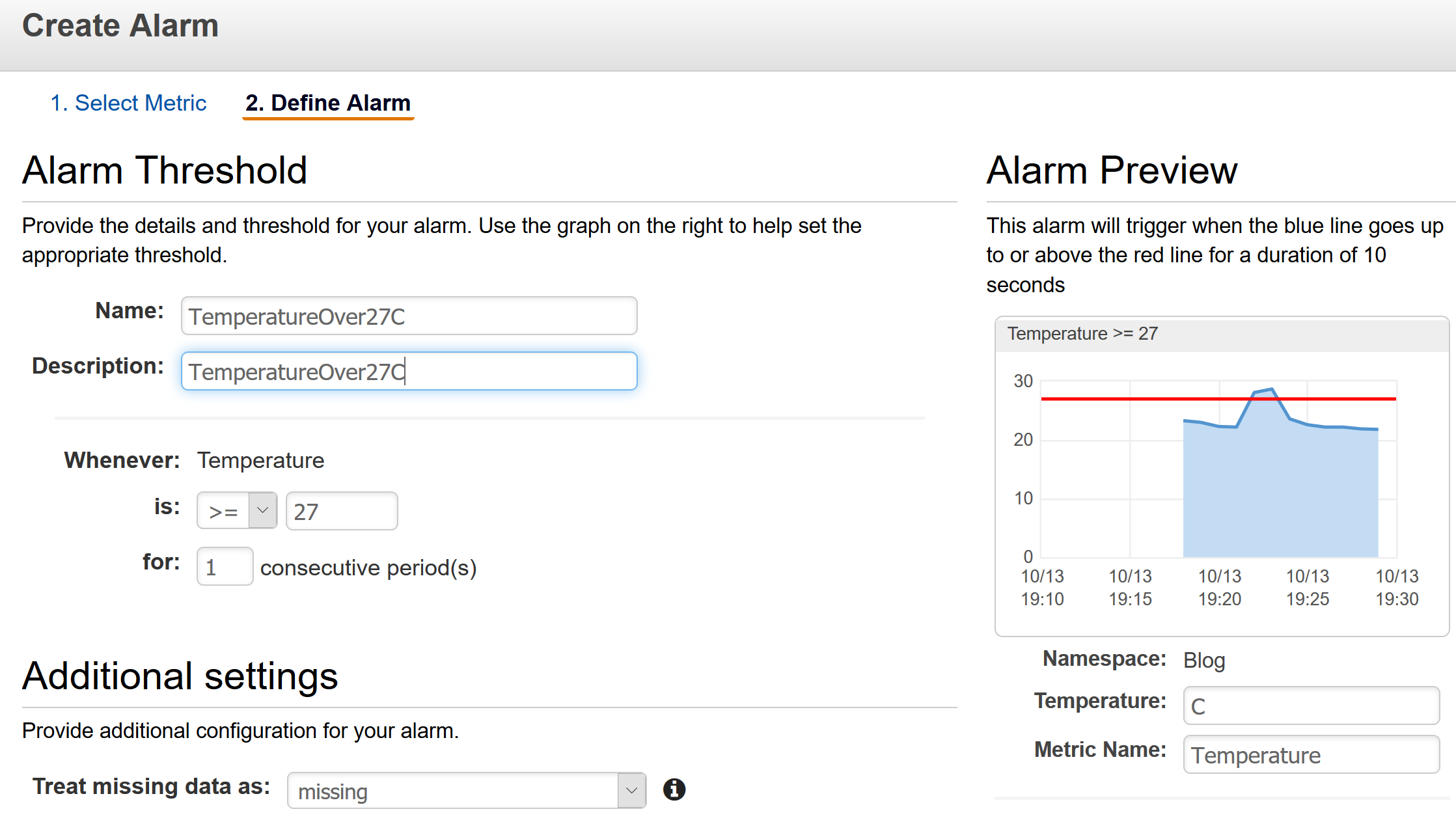
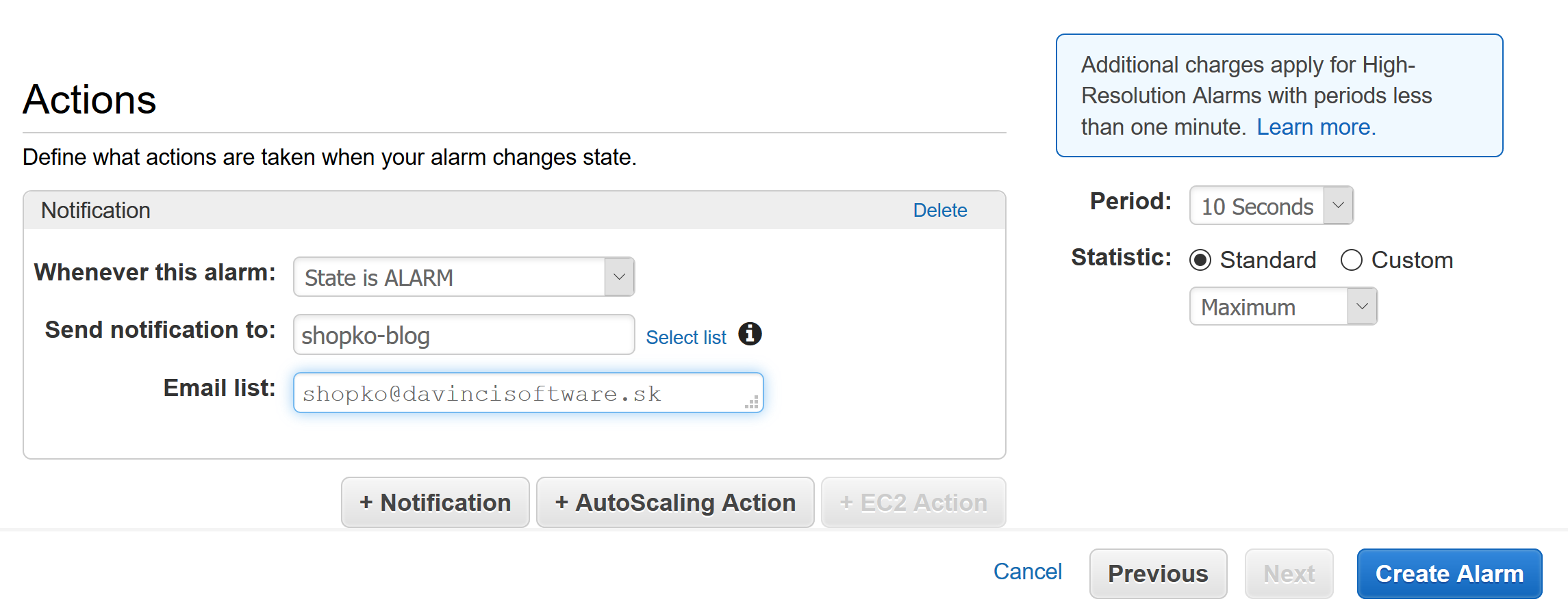
Now we need to setup alarms. For example, we would like to be informed immediately when the temperature reaches 27°. We will create alarm directly in AWS CloudWatch (little bell in Actions column) so SNS stuff is created for us automatically in the background. Pictures below show the desired configuration.
Now it is time for “touching the cloud” as mentioned at the beginning of this blog. We want to trigger the alarm now, so just hold they sensor with your fingers which should be warmer than your room’s temperature. As you are holding the sensor, your body temperature value is sent to the cloud. Shortly we will see a change of Alarm state in CloudWatch and also an e-mail will come.
![]()
![]()
Working with analog values is almost the same as with digital. Instead of working with values 0 and 1, we’re working with all values between 0 and 1. Isn’t it great to create something tangible and see it working in a few seconds? All the source codes are downloadable on the bottom of this blog.
With this blog, I wanted to show you how simple it is to begin with the Internet of Things and connect software with hardware. I’m not saying that the whole technology or electronics are simple, but I think that there are huge possibilities of what you can create with a very little knowledge. There are almost unlimited options once you dive deeper.
I would also recommend you to look at the smaller brothers of devices like Raspberry Pi, for example Raspberry Pi Zero or Pocket Beagle. They are super small and should be also much cheaper with almost the same capabilities.
If you have any questions regarding IoT basics or connection with AWS don’t hesitate to contact me, I will be happy to help you.
Here you can download the mentioned source codes.
And let me know how you succeeded at shopko@davincisoftware.sk.
Good luck!
Do you see yourself working with us? Check out our vacancies. Is your ideal vacancy not in the list? Please send an open application. We are interested in new talents, both young and experienced.
Join us